Tuesday, 11 March 2008

TUNER PROBLEMS AND SOLUTIONS.

No reception from antenna or cable:
Make sure your source is providing a signal and that the cable connectorsare good (center pin not broken or bent). Try another TV if possible. Make sure you source select switch or mode is set correctly. Someonemay have accidentally set it to direct video or AUX input. Are all bands affected? If so, the tuner or IF is faulty. If there isa lot of snow, then it is probably toward the front (circuitry wise) ofthe tuner. If it is just a black screen, then it could be in the IF orvideo amplifier. If only certain bands are bad - channels 2-6 for example, then certainparts of the tuner circuitry are faulty. However, make sure the CATVmode is set correctly as this affects reception on a band-by-band basis. The problems may be due to bad solder connections of the tuner shields,connectors, coils, and other components. Try prodding the tuner to seeif you can make the problem come and go or at least change.

Missing or noisy channel or block of channels:
If you are unable to receive certain channels or blocks of channels,this is a tuner problem - could be as simple as bad connections - oreven simpler:. First, check to see that the tuning mode is correct - TV, CATV, asthis is the most common cause of channels 'disappearing'. TV channels are assigned frequencies ranging from 72 to almost 800 MHzdepending on broadcast or cable channel assignment. To tune over such a wide range requires splitting it up into various bands even if these are not actually defined. If you have a varactor tuned set, then you already know about the Vl, Vh, and U bands which may use separate front-end components. Even modern quartz PLL synthesized tuners need to allocate circuitry depending on frequency range. Therefore, if a block channels is not working, it could be due to a failure of some component related to that frequency range. Aside from looking for bad connections, resoldering the shields and connector pins, prodding, pressing, praying, etc. you will need a schematic to have any chance of finding such a fault. There is another slight possibility. Some TVs have a parental lockoutcapability (pre V-chip) to prevent kids or other unauthorized access toselected channels. The channel selections may have been accidentallyaltered. Check your user manual for instructions on programming thisfeature. Even on models without this option, the same internal circuitry could be present but not normally accessible. A power surge or stray cosmic ray could have put the set in a screwy mode. Unplugging power for a minute or probably a much longer time might possibly reset such an anomaly.

Loss of Channel after Warmup:
If there is a general loss of picture and sound but there is light on the screen, then most likely the tuner or IF stage is pooping out. With both no sound and no picture but a raster and static, it is mostlikely a problem in the tuner, power to the tuner, or its controller(if non-knob type). If it recovers after being off for a while, then you need to try a coldspray in the tuner/controller to identify the component that is failing.Take appropriate safety precautions while working in there! If it stays broken, then most likely some component in the tuner, itscontroller, or its power supply as failed. There is a slight chance that it could be a bad solder connection - I have seen these in the tuner modules of RCAs on several occasions (and many other manufacturers – apparently not a solved manufacturing problem even after 40+ years! Channel tuning drifts as set warms up: This may be a slight drift - like someone is messing with the fine tuning or such a substantial change in tuning frequency that the channels go by as though you are surfing. Possible causes depend on tuner type:
1. Quartz tuner (10 button direct access digital synthesizer) - For a slight drift, a component is probably changing value, possibly the crystal in the reference oscillator. For gross changes - flipping through channels - it is more likely to be a digital control problem -the microcontroller is misdirecting the synthesizer to change frequency.
2. Varactor tuner (buttons but not direct channel access) - If only a single pushbutton selection is the problem, the the varactor tuning diode for that button is probably changing capacitance. If all channels ina band (Vl, Vh, U) are having a problem, it is more likely to be a drifting D/A or faulty AFT (Automatic Fine Tuning) circuit or power supply.
3. Turret or switch tuner (Knobs) - A component like a capacitor is changing value. You will have to get in there with a heat gun or cold spray and track it down the old fashioned way. At least, the problem is almost certainly localized to the tuner box (and possibly the controller if applicable). As noted, gradual slight changes in tuning are likely due to frequencydetermining components drifting. Uncontrolled channel surfing is probably a logic problem. For thequartz tuner, this could still be marginal connections causing themicroprocessor to misdirect the synthesizer to change channels. For the latter case, particularly, the cause may still be bad connections resulting in loss of channel memory and/or erratic behavior.

No reception from antenna or cable
Make sure your source is providing a signal and that the cable connectorsare good (center pin not broken or bent). Try another TV if possible. Make sure you source select switch or mode is set correctly. Someonemay have accidentally set it to direct video or AUX input. Are all bands affected? If so, the tuner or IF is faulty. If there isa lot of snow, then it is probably toward the front (circuitry wise) ofthe tuner. If it is just a black screen, then it could be in the IF orvideo amplifier. If only certain bands are bad - channels 2-6 for example, then certainparts of the tuner circuitry are faulty. However, make sure the CATVmode is set correctly as this affects reception on a band-by-band basis. The problems may be due to bad solder connections of the tuner shields,connectors, coils, and other components. Try prodding the tuner to seeif you can make the problem come and go or at least change. Picture is overloaded, washed out, or noisy This indicates an Automatic Gain Control (AGC) problem often caused bya dried up capacitor. You will probably need a schematic to go muchfurther. This could be a problem in the tuner, IF, or video amplifiers.

Interference when using VCR RF connection
(Some of these comments also apply to use of Laserdisc players, satellitereceivers, video games, or other sources with RF modulator (Channel 3/4)outputs). This may consist of patterns or lines in the picture. If this only happens on the antenna or cable, it may be a problemwith these sources or the tuner in the VCR rather than the TV.As a test, try the connecting the TV directly to the antenna or cable. If it only happens on cable, there may be a (temporary) problem withcable transmission - contact your cable company. If it happens on playback of good quality (commercial) recordings, thenit could be a compatibility problem between the VCR and TV. Make sure your patch cable connections are secure and that the cablesare not damaged - in particular that the center pin is intact. Try fine tuning if your TV has this capability. If this does nothelp, try switching the channel 3/4 selector on the VCR to the oppositeposition and try that channel, sometimes one will be better than the otherparticularly if one of these or an adjacent channel is active in your area. If you have RCA baseband video inputs on your TV, try this connection tothe VCR. These should work better in any case. Confirm that it is not actually a problem with the VCR - try another TVif possible. If you just changed your component placement, the VCR or TV may bepicking up interference from another component. Turn off everything butthe VCR and TV and see if that identifies the culprit. Move the TVaway from the VCR so see if they are interfering with each other - theTV may be introducing interference into the VCR. Occasionally, the particular patch cable or its length may affectreception quality - try another one. If none of this helps, you VCR's RF modulator may be bad or slightlyweak. Alternatively, the tuner in the TV may be faulty. If receptionis generally noisy on all sources, AGC or RF/IF alignment may needadjusting. However, not all tuners are created equal. Your TV maysimply be making the best of a marginal situation. A light dimmer on the same circuit as the TV may result in similarsymptoms. If you are tuning up your motorcycle (or automobile) in thesame room, this may be spark ignition interference.

Missing or noisy channel or block of channels
If you are unable to receive certain channels or blocks of channels,this is a tuner problem - could be as simple as bad connections - oreven simpler:. First, check to see that the tuning mode is correct - TV, CATV, asthis is the most common cause of channels 'disappearing'. TV channels are assigned frequencies ranging from 72 to almost 800 MHzdepending on broadcast or cable channel assignment. To tune over such awide range requires splitting it up into various bands even if these arenot actually defined. If you have a varactor tuned set, then you alreadyknow about the Vl, Vh, and U bands which may use separate front-endcomponents. Even modern quartz PLL synthesized tuners need to allocatecircuitry depending on frequency range. Therefore, if a block channels isnot working, it could be due to a failure of some component related to thatfrequency range. Aside from looking for bad connections, resoldering theshields and connector pins, prodding, pressing, praying, etc. you will needa schematic to have any chance of finding such a fault. There is another slight possibility. Some TVs have a parental lockoutcapability (pre V-chip) to prevent kids or other unauthorized access toselected channels. The channel selections may have been accidentallyaltered. Check your user manual for instructions on programming thisfeature. Even on models without this option, the same internal circuitrycould be present but not normally accessible. A power surge or stray cosmicray could have put the set in a screwy mode. Unplugging power for a minute or probably a much longer time might possibly reset such an anomaly. Loss of Channel after Warm up If there is a general loss of picture and sound but there is light on thescreen, then most likely the tuner or IF stage is pooping out. With both no sound and no picture but a raster and static, it is mostlikely a problem in the tuner, power to the tuner, or its controller(if non-knob type). If it recovers after being off for a while, then you need to try a coldspray in the tuner/controller to identify the component that is failing.Take appropriate safety precautions while working in there! If it stays broken, then most likely some component in the tuner, itscontroller, or its power supply as failed. There is a slight chance thatit could be a bad solder connection - I have seen these in the tuner modulesof RCAs on several occasions (and many other manufacturers - apparentlynot a solved manufacturing problem even after 40+ years!

Channel tuning drifts as set warms up
This may be a slight drift - like someone is messing with the fine tuningor such a substantial change in tuning frequency that the channels go byas though you are surfing. Possible causes depend on tuner type: Quartz tuner (10 button direct access digital synthesizer) - For a slight drift, a component is probably changing value, possibly the crystal in the reference oscillator. For gross changes - flipping through channels - it is more likely to be a digital control problem - the microcontroller is misdirecting the synthesizer to change frequency. Varactor tuner (buttons but not direct channel access) - If only a single pushbutton selection is the problem, the the varactor tuning diode for that button is probably changing capacitance. If all channels in a band (Vl, Vh, U) are having a problem, it is more likely to be a drifting D/A or faulty AFT (Automatic Fine Tuning) circuit or power supply. Turret or switch tuner (Knobs) - A component like a capacitor is changing value. You will have to get in there with a heat gun or cold spray and track it downthe old fashioned way. At least, the problem is almost certainly localizedto the tuner box (and possibly the controller if applicable). As noted, gradual slight changes in tuning are likely due to frequencydetermining components drifting. Uncontrolled channel surfing is probably a logic problem. For thequartz tuner, this could still be marginal connections causing themicroprocessor to misdirect the synthesizer to change channels. For the latter case, particularly, the cause may still be bad connectionsresulting in loss of channel memory and/or erratic behavior.

Noise in picture and sound due to bright scene
When a bright scene comes, the screen flashes and there is a lotof noise in the sound. When a dark scene comes, there is no flash or noise. Changing channel does not help. The noise persists even when the sound is muted. (The following is from: Lattuca@Midwest.net (Sam Lattuca)) When the video detector level is adjusted too high, you will get noise in the sound while screen contains a lot of white information (i.e. letters) but won't when only dark scenes are present. The video level adjust is usually a small coil normally located near the IF section. Since your set is several years old, this wouldn't be uncommon. It can be adjusted while watching the picture and listening to the sound.


REFERENCE:
http://www.stedmundsbury.gov.uk/sebc/play/tvprobs.cfm.
http://www.epanorama.net/links/repair.html#tv.
http://www.basementarcade.com/arcade/library/tvrepair.txt
TV POWER SUPPLY PROBLEMS AND SOLUTIONS .


TV power cycling on and off:


The power light may be flashing or if you are running with a serieslight bulb it may be cycling on and off continuously. There may bea chirping or clicking sound from inside the set. (Note: using too small series light bulb load during testing for the size of the TV may also result in this condition.) If there is a low voltage regulator or separate switching supply, itcould be cycling on and off if the horizontal output, flyback, orone of its secondary loads were defective. Does this TV have a separate low voltage regulator and/or switching power supply or is it all part of the flyback circuit? For the following, I assume it is all in one (most common). Some simple things to try first: Verify that the main filter capacitor is doing its job. Excessive ripple on the rectified line voltage bus can cause various forms of shutdown behavior. An easy test is to jumper across the capacitor with one of at least equal voltage rating and similar capacitance (make connections with power off!). Use a Variac, if possible, to bring up the input voltage slowly and see if the TV works at any point without shutting down. If it does, this could be an indication of X-ray protection circuit kicking in, though this will usually latch and keep the set shut off if excessive HV were detected.


TV turns off after warming up:


If you can turn it back on with the s momentary key or power button: When it shuts off, do you need to push the power button once or twiceto get it back on? Also, does anything else about the picture or soundchange as it warms up?

1. If once, then the controller is shutting the TV down either as a result of a (thermally induced) fault in the controller or it sensing some other problem. Monitoring the voltage on the relay coil (assuming these is one) could help determine what is happening. The controller thinks it is in charge.

2. If twice, then the power supply is shutting down as the controller still thinks it is on and you are resetting it. A couple of possibilities here would be low voltage or high voltage regulation error (excessive high voltage is sensed and causes shutdown to prevent dangerous X-ray emission). A partially dried up main filter capacitor could also cause a shutdown but there might be other symptoms like hum bars in the picture just before this happened. Clipping a good capacitor across the suspect (with power off!) would confirm or eliminate this possibility. If it uses a pull-knob (or other hard on/off switch), then this may be like pulling the plug and would reset any abnormal condition.


TV doesn't power up immediately:


The TV may do nothing, cycle on and off for a while, power up and thenshutdown in an endless cycle - or at least for a while. Then it comeson and operates normally until it is turned off. A couple of possibilities:

1. The main filter capacitor or other filter capacitors in the low voltage power supply is dried up and this can cause all kinds of regulation problems.

2. The power supply regulator is defective (or marginal) allowing excessive voltage on its output and then the X-ray protection circuitry shuts you down. If you can get access to a Variac, it would be worth bringing up the input voltage slowly and seeing if there is some point at which it would stay on. If there is, then if the picture has serious hum bars in it the main filter cap could be bad. If more or less a decent picture with minor hum bars then it could be the regulator.


Arcing from flyback or vicinity:


Arcing may be visible or audible and result in readily detectable levels of ozone. Note that very slight traces of ozone may not indicate anything significant but if the TV smells like an office copier, there is probably some discharge taking place. WARNING: It is possible for arcing to develop as a result of excessive high voltage. Symptoms might be a smaller than normal excessively bright picturebut this may not be able to be confirmed until the flyback is repaired or replaced. See the section: "Excessive high voltage".

* On the HV output, it will probably be a loud snapping sound (due to the capacitance of the CRT) with associated blue/white sparks up to an inch or more in length. If the arc length is short enough, this may turn into a nearly continuous sizzling sound with yellow/orange arc and melting/burning plastic.

* Prior to the HV rectifier, it will likely be a continuous sizzle with orange/yellow/white arc and melting/burning plastic or circuit board material.

* Internal arcing in the flyback may be audible and eventually result in a bulging and/or cracked case (if some other component doesn't fail first as this would take some time to develop).

* A corona discharge without actual sparks or a visible well defined arc is also possible. This may be visible in a totally dark room, possibly more likely when the humidity is high. A thorough cleaning to remove all dust and grime may be all that is needed in this case.

* If the arc is coming from a specific point on the flyback - a crack or pinhole - this may be patched well enough to confirm that the rest of the TV is operational and a new flyback is worth the money. Otherwise, there is no way of knowing if the arcing may have damaged other circuitry until a replacement flyback - possibly money wasted - arrives. To attempt a repair, scrape off any dirt or carbon that is present along the path of the arcing and its vicinity. Then, clean the area thoroughly with alcohol and dry completely. Otherwise, the dirt and carbon will just act as a good conductor and the arcing will continue under your repair! Several layers of plastic electrical tape may be adequate for testing. Multiple coats of high voltage sealer or non-corroding RTV silicone (if it smells like viniger - acetic acid - as it cures, this may get in and affect the windings) would be better if the objective is an actual repair. This may prove to be a permanent fix although starting the search for a source for a new flyback would not hurt just in case. The arc most likely did damage the insulation internally which may or may not be a problem in the future. Also see the section: "Dave's complete procedure for repair of an arcing flyback".
* In some cases, the pinhole or crack is an indication of a more serious problem - overheating due to shorted windings in the flyback or excessive secondary load.

* If the arc is from one of the sparkgaps around the CRT or the CRT socket, this could also be a flyback problem indicating internal shorts in the focus/screen network.

* If the arcing is inside the CRT, this could indicate a bad CRT or a problem with the flyback focus/screen network and no or inadequate sparkgap protection. Where repair seems possible, first, clean the areas around the arc thoroughlyand then try several layers of plastic electrical tape. If the TV works normally for say, an hour, then there is probably nothing else wrong and youcan try for a proper sealing job or hope that tape holds out (put a few more layers on - each is good for about 8-10 KV theoretically). However, replacement of the flyback really is the best alternative to minimizerisk of future problems. This is the only option where there could be a potential issue of liability should subsequent failure result in a fire. Once I had a TV where the main problem was a cracked flyback arcingbut this took out one of the fusable resistors for the power supply to the *vertical.* output so the symptoms included a single horizontal line.Don't ask me to explain - replacing that resistor and the flyback (theflyback tested good, but this was for someone else) fixed the TV. In another case, a pinhole developed in the flyback casing probablydue to poor plastic molding at the time of manufacture. This resulted in a most spectacular case of sparking to a nearby bracket. A few layers of electrical tape was all that was needed to affect a permanent repair


REFERENCE :
http://www.stedmundsbury.gov.uk/sebc/play/tvprobs.cfm.
http://www.epanorama.net/links/repair.html#tv.
http://www.basementarcade.com/arcade/library/tvrepair.txt

Thursday, 6 March 2008

remote control


KINDS REMOTE CONTROL.


INTRODUCTION .
Wireless remote controls are control devices that allow you to activate certain functions on a device without having to physically activate the device yourself or having a cable connected to it. The wireless remote controls allow you to perform these functions from a distance away with a battery operated device and not with any cables. The wireless remote control systems can be used for many different purposes. You can find wireless remote control for lamp switches, wireless remote controls for winch and wireless remote control for iPods. The wireless remote control for iPods allows you to run the controls on the iPods from a distance away. These wireless controls allow you change songs, rewind or fast forward without having to be right next to the iPod.


HISTORY
The first remote intended to control a television was developed by Zenith Radio Corporation in 1950. The remote — officially called "Lazy Bones" was connected to the television set by a wire. To improve the cumbersome setup, a wireless remote control called "Flashmatic" was developed in 1955 which worked by shining a beam of light onto a photoelectric cell. Unfortunately, the cells did not distinguish between light from the remote and light from other sources and the Flashmatic also required that the remote control be pointed very accurately at the receiver.


The Zenith Space Commander 600 remote control
In 1956 Robert Adler developed "Zenith Space Command", a wireless remote. It was mechanical and used ultrasound to change the channel and volume. When the user pushed a button on the remote control it clicked and struck a bar, hence the term "clicker". Each bar emitted a different frequency and circuits in the television detected this noise. The invention of the transistor made possible cheaper electronic remotes that contained a piezoelectric crystal that was fed by an oscillating electric current at a frequency near or above the upper threshold of human hearing, though still audible to dogs. The receiver contained a microphone attached to a circuit that was tuned to the same frequency. Some problems with this method were that the receiver could be triggered accidentally by naturally occurring noises, and some people, especially young women, could hear the piercing ultrasonic signals. There was even a noted incident in which a toy xylophone changed the channels on these types of TVs since some of the overtones from the xylophone matched the remote's ultrasonic frequency.


Jerrold remote control by General Instrument from the late 1970s
The impetus for a more complex type of television remote control came in the late 1970s with the development of the Ceefax teletext service by the BBC. Most commercial remote controls at that time had a limited number of functions, sometimes as few as three: next channel, previous channel, and volume/off. This type of control did not meet the needs of teletext sets where pages were identified with three-digit numbers. A remote control to select teletext pages would need buttons for each number from zero to nine, as well as other control functions, such as switching from text to picture, and the normal television controls of volume, station, brightness, colour intensity and so on. Early teletext sets used wired remote controls to select pages but the continuous use of the remote control required for teletext quickly indicated the need for a wireless device. So BBC engineers began talks with one or two television manufacturers which led to early prototypes in around 1977-78 that could control a much larger number of functions. ITT was one of the companies and later gave its name to the ITT protocol of infrared communication.


OPERATION.


Inside a TV Remote Control

If you are like most Americans, you probably pick up a TV remote control at least once or twice a day. Let's look inside and see how they work. Here is the remote we will be dissecting today:


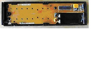
The remote control's job is to wait for you to press a key, and then to translate that key-press into infrared (pronounced "infra-red") light signals that are received by the TV. When you take off the back cover of the control you can see that there is really just 1 part visible: a printed circuit board that contains the electronics and the battery contacts .


The components that you see here are typical for most remotes. You can see an integrated circuit (also known as a chip) labeled "TA11835". The chip is packaged in what is known as an 18 pin Dual Inline Package, or a DIP. To the right of the chip you can see a diode, a transistor (black, with three leads), a resonator (yellow), two resistors (green) and a capacitor (dark blue). Next to the battery contacts there is a resistor (green) and a capacitor (tan disk). In this circuit, the chip can detect when a key is pressed. It then translates the key into a sequence something like morse code, with a different sequence for each different key. The chip sends that signal out to the transistor to amplify the signal and make it stronger.
Wave the TV remote control goodbye and change channel with a thumbs-up.


Not only will it be a godsend for lazy viewers, it could also save hours of fruitless scrabbling among the sofa in search of the remote control.
The all-seeing wave controller is the brainchild of Australian engineers Dr Prashan Premaratne and Quang Nguyen.
They believe it could be on sale within three years, ending the frustration involved in finding and using remote controls.
Dr Premaratne, of the University of Wollongong, said: "We all rely on remote controls to manage an increasing number of items including TVs, set-top boxes, DVDs and hi-fis, and the range of goods will continue to increase.
"Apart from the frustration of sometimes mislaying the remote control just when you need it, they do tend to have different sets of commands which have to be mastered.
"People have tried to replace remote controls with voice recognition or glove-based devices but with mixed results."

The device is designed to sit on a shelf or table which has a clear line of sight to the television and the owner.
Its software recognises simple, deliberate hand gestures and then sends the appropriate signal to a universal remote control, designed to work with most makes of television, video recorder, DVD player, hi-fi and digital set-top box.
In tests, published in the Institution of Engineering and Technology's Computer Vision Research Journal, a prototype worked in all kinds of lighting, and at a range of distances.
It was able to switch equipment on and off, alter the volume, change channels, play and stop. Dr Premaratne says anyone can learn the gestures within five minutes.
One is used to tell the device which item you want to switch on or adjust.
A clenched fist means "start", an outstretched hand with closed fingers means "power on", a thumbs-up sign means "up" and a sideways victory sign means "channel".
Crucially for anyone with small children, pets or gesticulating family members, the software can distinguish between real commands and unintentional gestures. The team has started work on making the gadget small enough to be built in to televisions or other devices.
They also want to adapt it for use with computer games consoles. Dr Premaratne said: "Normal game consoles rely on pressing series of buttons to get commands.
"Hand gestures can replace those button presses and the gaming experience will be truly revolutionized."


EXAMPLES OF REMOTE CONTROLS.


Monday, 3 March 2008

ANTENNA TYPES.
DEFINATION :
An antenna is a transducer, i.e. a “converter” between two media. The antenna converts electromagnetic energy in a cable into electromagnetic radiated power in free space.
Various characteristics of the antenna determine”how efficient” this conversion is performed:

ANTENNA CHARACTERISTICS.
1.To have as much energy as possible carried on as radiation in the room is of great importance, i.e. the antenna should not be capable of consuming energy itself.

2.It is important that the antenna concentrates its radiated energy as efficiently as possible in the required way.it If so, either a wide coverage range or a reduced transmitting power can be achieved, until the range is exactly suiting the one required.


The antenna converts electromagneticenergy
in a cable into electromagneticradiated power in free space

Omni directional Antenna


Directional Antenna

Antenna Types

1. Base Station Antennas
2. Antennas for movable units

Base Station Antennas :
Base station antennas can be:
· Omnidirectional Antennas
· Directional Antennas
· Antennas with radiation being specially constructed, the latter yielding the antenna a quite specific coverage range

Antennas for movable (”mobile”) units
· ”Mobile” antennas can be split up into: Land Mobile Antennas (vehicle antennas)
· Marine Antennas (for ships)
· Portable Antennas (antennas for portable communication equipment)
· (Air Craft Antennas) .


"Mobile" antennas can be split up into:
1. Land Mobile Antennas (vehicle antennas)
2. Marine Antennas (for ships)
3. Portable Antennas (antennas for portable communication equipment) (Air Craft Antennas) .


Examples:
Base Station Antennas


Base Station Antenna
"Mobile” antennas

Land Mobile Antenna

NB Colloquially, the word ”mobile antenna” is usually used as designation for a vehicle antenna.


Marine Antenna
Portable Antenna


Air Craft Antenna

Portable Antenna

How to describe how good an antenna is?

The four ”figures” describe how good an antenna is compared to the required performance:

· SWR = Standing wave ratio .
· D = Directivity .
· G = Gain .
· BW = Bandwidth .

SWR .
If the impedance of the antenna is different from the impedance of the cable, the antenna will reflect back some of the induced energy through the feeder cable to the transmitter, which naturally is undesirable.Normally, the impedance of the cable is 50 Ω. If Ra indicates the impedance of the antenna, the standing wave ratio is defined as:SWR = Ra/50 Ω (if Ra is more than 50 Ω)SWR = 50/Ra Ω (if Ra is less than 50 Ω)Examples:If Ra = 50 Ω is SWR = 1.0If Ra = 100 Ω is SWR = 2.0If Ra = 25 Ω is SWR = 2.0Consequently, it is of importance that the SWR is as close to 1.0 as possible thus obtaining the highest power being transmitted from the cable to the antenna.

Directivity D .
The directivity D is an indication of the capability of the antenna to conduct the radiated power “to a certain site”.Normally, omnidirectional or directional antennas are mentioned.
Omnidirectional:
An omnidirectional antenna with high directivity has a radiation being similar to a pancake.


Directional:
A directional antenna with high directivity has a radiation being similar to the cone of light from a projector.

Gain G .
The gain of an antenna is defined as G = η x D, where η indicates the efficiency of the antenna.Consequently, in the gain value possible loss in the antenna is comprised. The η-figure is always less than the directivity.For most antenna types the own loss is so low that G = D can be considered.

Bandwidth .
The bandwidth of the antenna is the frequency range, in which it operates properly,i.e. both gain and SWR are within the more specified limits.

How to measure how good an antenna is?
The performance of an antenna can be determined from the following formula:
· SWR = Standing Wave Ratio
· G = Gain
· BW = Bandwidth
The following explains how to determine SWR, Gain og BW


Measuring SWR.
Standing Wave Ratio:
The standing wave ratio is normally measured by inserting adevice in the feeder cable of the antenna. How much powerreflected back from the antenna compared to the powertransmitted forward is measured?Such a device is called a directional coupler.Directional couplers:Directional couplers or SWR meters for frequencies lower than150 MHz are relatively cheap and quite accurate.For frequencies above 400 MHz exact meters are expensive.The most well known universal instrument is a BIRD-wattmeter.

Measuring the standing wave ratio .

Measuring gain .
The gain of an antenna is measured in relation to the gain of another further specified antenna through a comparison measurement.The latter antenna is called a reference antenna and the reference antenna is different, irrespective of weather base station antennas,mobile antennas or portable antennas are considered.


Measurement setup/procedure .

Measuring BW.
The bandwidth is generally specified as the area of the lowest part of the frequency ranges, in which SWR and gain observe the specifications
¼ wave and collinear at the car roof centre.

COMMON TV ANTENNAS.
The Dipole
This is the simplest TV antenna. Variations on the dipole are the bowtie (which has wider bandwidth), the folded-dipole (which can solve an efficiency problem) and the loop (a variation on the folded dipole). All four have the same gain and the same radiation field: a torroid (doughnut shape). The gain is generally 2.15 dBi. “dBi” means “dB of improvement over an isotropic radiator”, which is an antenna that radiates equally in all directions. This sounds like a discussion of transmitting antennas, and it could be. An antenna will have the same gain when receiving as when transmitting, and also the same radiation pattern.


The dipole has positive gain because it does not radiate equally in all directions. This is a universal truth. To get more gain, an antenna must radiate in fewer directions. Imagine a spherical balloon. Now press on it from opposite sides with a finger of each hand. Push in until your fingers meet. The result looks like the torroid above. But more importantly, the balloon expanded in the other directions. A-hah! Gain! That’s the way antennas work.

Keep this balloon analogy in mind. More complicated antennas work by reducing radiation in most directions. They distort the balloon considerably, but the volume of the balloon remains constant.

Another rating system for antennas uses dBd, which means dB of improvement over a dipole antenna. To convert dBd to dBi, just add 2.15. Antenna makers specify their gains in dB. They actually mean dBd, but given the way they exaggerate their claims, dBi is usually closer to the truth.

In the US, TV antennas are always horizontal. If you rotate an antenna about the forward axis (a line from the transmitting antenna) the signal strength will vary as the cosine of the angle. In other words, when the antenna elements are vertical, no signal is received because TV signals have horizontal polarization.

Yagi Antennas .
A Yagi antenna has several elements arranged in echelon. They are connected together by a long element, called the boom. The boom carries no current. If the boom is an insulator, the antenna works the same.
The rear-most element is called the reflector. The next element is called the driven element. All the remaining elements are called directors. The directors are about 5% shorter than the driven element. The reflector is about 5% longer than the driven element. The driven element is usually a folded dipole or a loop. It is the only element connected to the cable. Yet the other elements carry almost as much current.

The Yagi is the most magical of all antennas. No attempt will be made here to explain why it works. The more directors you add, the higher the gain becomes. Gains above 20 dBi are possible. But the Yagi is a narrowband antenna, often intended for a single frequency. As frequency increases above the design frequency, the gain declines abruptly. Below the design frequency, the gain falls off more gradually. When a Yagi is to cover a band of frequencies, it must be designed for the highest frequency of the band.

An antenna has an aperture area, from which it captures all incoming radiation. The aperture of a Yagi is round and its area is proportional to the gain. As the leading elements absorb power, diffraction bends the adjacent rays in toward the antenna.

The formula for the aperture area of any TV antenna is A=Gl2/4p where l is the wavelength and G is the gain factor over an isotropic antenna (not dB).

The bandwidth of a Yagi can be increased by sizing the reflector for the lowest frequency of the band while sizing the directors for the highest. But this decreases the best gain of the antenna. (It is said that the gain-bandwidth product remains the same.) A better way to increase the bandwidth is to replace the reflector element with a corner-reflector assembly.


This boosts the performance on the lower numbered channels without hurting the high channels. Although the Yagi/Corner-Reflector might not be the best antenna, it is the most common UHF TV antenna, mainly because it can be mounted on the front of a VHF antenna without degrading the VHF antenna.

A UHF Yagi today is designed for channel 69. If you see an old Yagi, it might be intended for channel 82. In the future they will be cut for channel 51. It is not possible to tell by looking at a Yagi which era it belongs to, so be careful.


Radiation patterns :


As you can see, the 8-Bay is a very directional antenna. If miss-aimed by 5° you can lose 1 dB of signal. If the skyline is more than 5° above horizontal, you should tilt the antenna up to point at the skline.

The overhead view shows nulls at 30° and 90° to both sides. These can be used to eliminate multi-path (ghosts) or interference. You simply rotate the antenna until the offending signal is in one of the nulls.


A Yagi also has some forward nulls that can be used as ghost killers. But a Yagi/Corner-Reflector acts more like a corner reflector for most channels, and has no nulls. At channel 60 you can finally see the Yagi pattern start to emerge.

This author prefers the 8-Bay over the Yagi/Corner-Reflector because
It has high gain.
Its gain is evenly distributed over the channels.
It has nulls that can eliminate multi-path.
It has a rectangular aperture that permits efficient stacking when more than 8 bays are necessary.

But the high gain means it is hard to aim. In good-signal areas, avoid high gain antennas.

REFERENCE:

http://www.kyes.com/antenna/environment.html
http://www.bbc.co.uk/reception/analoguetv/picture.shtml
http://www.hdtvprimer.com/


Tuesday, 19 February 2008

FREQUENCY ALLOCATION TABLE.
INTRODUCTION:
For efficiency in transmission of both radio and television waves the should be a standard bandwidth of frequency to be used as guideline. Failure of which is an offence punishable by law. These frequencies are allocated according to use e.g. television channel, radio stations and aeronautical channels,
Broadcasting ,aeronautical radio navigation ,aeronautical mobile ,space navigation and space research , mobile ,amateur and amateur satellite mobile, maritime mobile National Television Standards Committee (NTSC) is the standards that is mostly followed.


CONCLUSION.
Frequencies for different use are allocated as follows.


REFERENCE
www.projects.com
www.digchip.com
www.eporonaelec.com


TELEVISION BLOCK DIAGRAM AND FUNCTIONS:
INTRODUCTION:

A television receiver is made up of several function block which together functions to achieve a good signal reception ,color display, clear sound etc this blocks are shown below plus their functionality.


LCD TV
LCD TV is a digital television system that displays digital video on an LCD (Liquid Crystal Display) and supports digital/analog video broadcasting (cable, satellite, terrestrial), broadband connection, personal video recording (PVR), interactive internet, and wireless connectivity.
Core Subsystem includes:
DSP - performs MPEG encoder/decoder, video, voice/AC3/MPEG audio processing.
RF Demodulation - performs COFDM/QAM/QPSK demodulation, Forward Error Correction (FEC) and video mux.
MCU - controls system electronic, network, and user interface.
Memory - stores executing code and data/parameters.
Video Interface - selects video source to be decoded/encoded by ADC/DAC and DSP.
Audio Interface - allows audio to be digitized by the audio codec and processed by DSP to provide high-quality audio for MPEG/AC3 requirements.
LCD Interface - parallel digital video is converted into serial data for transmitting to the TFT (Thin Film Transistor) controller via the LVDS (Low-Voltage Differential Signaling) transmitters and receivers. The LCD display is controlled by the CCFL (Cold-Cathode Fluorescent Lamp) backlight and the TFT gate/source drivers.
Power Conversion - converts the input power from the AC adaptor to run various functional blocks.


A TV set includes the following functional blocks:

Low voltage power supply (some may also be part of (2).) Most of the lower voltages used in the TV may be derived from the horizontal deflection circuits. Sometimes, there is a separate switching power supply but this would be the exception. Rectifier/filter capacitor/regulator from AC line provides the B+ to the switching power supply or horizontal deflection system. Degauss operates off of the line whenever power is turned on (after having been off for a few minutes) to demagnetize the CRT.
Horizontal deflection. These circuits provide the waveforms needed to sweep the electron beam in the CRT across and back some 15,734 times per second (for NTSC). The horizontal sync pulse from the sync separator locks the horizontal deflection to the video signal.
Vertical deflection. These circuits provide the waveforms needed to sweep the electron beam in the CRT from top to bottom and back 60 times per second (for NTSC). The vertical sync pulse from the sync separator locks the vertical deflection to the video signal.
CRT high voltage (also part of (2).) A modern color CRT requires up to 30 kV for a crisp bright picture. Rather than having a totally separate power supply, nearly every TV on the planet derives the HV (as well as many other voltages) from the horizontal deflection using a special transformer called a 'flyback' or 'Line OutPut Transformer (LOPT) for those of you on the other side of the lake.

Tuner, IF, AGC, video and audio demodulators. Input is the antenna or cable signal and output are baseband video and audio signals. There is usually someplace inside the TV where line level video and audio are present but it may not be accessible from the outside of the cabinet unless you paid for the more expensive model with the A/V option. Very often, the tuner is a shielded metal box positioned on the bottom right (as viewed from the front) separate from the main circuit board. Sometimes it is on the main circuit board. The IF section may be in either place.
On older or cheap TVs with a knob tuner, this is usually mounted to the front panel by itself. There are usually separate boxes for the VHF and UHF tuners.
Chroma demodulator. Input is the baseband video signal. Outputs are the individual signals for the red, green, and blue video to the CRT.

Video drivers (RGB). These are almost always located on a little circuit board plugged directly onto the neck of the CRT. They boost the output of the chroma demodulator to the hundred volts or so needed to drive the cathodes of the CRT.

Sync separator. Input is baseband video. Output is horizontal and vertical sync pulses to control the deflection circuits.

Audio amplifier/output. The line level audio is amplified to drive a set of speakers. If this is a stereo TV, then these circuits must also perform the stereo demultiplexing.

System control. Most modern TVs actually use a microcontroller - a fixed program microcomputer to perform all user interface and control functions from the front panel and remote control. These are becoming increasingly sophisticated. However, they do not fail often. Older TVs use a bunch of knobs and switches and these are prone to wear and dirt.


conclusion
The vertical yoke is part of the host television set. Two coils make up the vertical yoke. These coils deflect the picture tube's electron beam in an up-and-down direction. The vertical yoke coils flank the sides of the picture tube neck.
The horizontal yoke, like the vertical yoke, is part of the host television set. The horizontal yoke includes two coils. These coils control side-to-side deflection of the electron beam. You'll find horizontal yoke coils above and below the picture tube neck.
Most problems occur in the horizontal deflection and power supply sections. These run at relatively high power levels and some components run hot. The high voltage section is prone to breakdown and arcing as a result of hairline cracks, humidity, dirt, etc.
The tuner components are usually quite reliable unless the antenna experiences a lightning strike. However, it seems that even after 20+ years of solid state TVs, manufacturers still cannot reliably solder the tuner connectors and shields so that bad solder connections in these areas are common even in new sets.


REFERENCE:
www.digchip.com
www.projects.com

Thursday, 14 February 2008


UNIVERSITY OF EASTERN AFRICA, BARATON.


SCHOOL OF SCIENCE AND TECHNOLOGY.


SUB- DEPARTMENT OF TECHNOLOGY.


ASSIGNMENT: COLOR TV PICTURE TUBE WITH LABELED PARTS


ASSIGNMENT PRESENTED IN PARTIAL FULLFILMENT OF THE COURSE: CMMT 381 TELEVISION CIRCUIT I.


PRESENTER: KIBARO ISAIAH.


ID. NUMBER: 05S0004.


INSTRUCTOR: PROF. JESSE ROLE


DATE AND PLACE: 14TH FEBRUARY 2008, BARATON UNIVERSITY.


INTRODUCTION.


In a color-television tube, three electron guns (one each for red, green, and blue) fire electrons toward the phosphor-coated screen. The electrons are directed to a specific spot (pixel) on the screen by magnetic fields, induced by the deflection coils. To prevent “spillage” to adjacent pixels, a grille or shadow mask is used. When the electrons strike the phosphor screen, the pixel glows. Every pixel is scanned about 30 times per second.


HISTORY. Crooke’s tube (OLD)


Sir William Crooke’s constructed this forerunner of the modern television picture tube in the 1870s to investigate the properties of cathode rays. When the tube is evacuated and a high voltage applied, one end of the tube glows, caused by cathode rays (now known to be electrons) striking the glass. The modern television picture tube, also known as a CRT (Cathode Ray Tube) is a direct descendant of the Crooke’s tube. The major differences are that a CRT uses a heated cathode to increase the number of electrons, while the Crooke’s tube does not, and the CRT has extra electrodes to focus and deflect the beam as it travels toward the screen. FIGURE 1


Color TV picture tube (MODERN).


A color television picture tube contains three electron guns, one corresponding to each of the three primary colors of light—red, green, and blue. Electromagnets direct the beams of electrons emerging from these guns to continuously scan the screen. As the electrons strike red, green, and blue phosphor dots on the screen, they make the dots glow. A screen with holes in it, called a shadow mask, ensures that each electron beam only strikes phosphor dots of its corresponding color. The glow of all the dots together forms the television picture. FIGURE 2a and FIGURE 2b


Trinitron Cathode Ray Tube.


Many televisions still use cathode ray tubes (CRTs) for receivers. Until the Sony Corporation patented the simplified Trinitron system in the late 1960s, RCA’s original and more complex color tube dominated the market. Today, flat-screen TVs, based on a different technology, are becoming increasingly popular. Electron gun electrode structure that produces and may control, focus, and deflect a beam of electrons, as in a television picture tube, here the beam produces a visual pattern on the tube's screen. The source of the electron beam is the cathode, a flat metal support covered with oxides of barium. Cathode-ray tube Vacuum tube that produces images when its phosphorescent surface is struck by electron beams.


figures


FIGURE 3


FIGURE 2b


FIGURE 2a


REFERENCE:
Encyclopedia Britannica.
Britannica Concise Encyclopedia.
www.digchip.com